7 3 Powerstroke Idm Wiring Diagram

7 3 Powerstroke Wiring Diagram Google Search With Images

7 3 Powerstroke Wiring Diagram Crayonbox Co With Images

Image Result For 7 3 Powerstroke Wiring Diagram Diagram Ford
Idm Wiring Issue Ford Powerstroke Diesel Forum
13416 7 3 Powerstroke Wiring Harness Wiring Resources

7 3 Powerstroke Wiring Diagram Google Search With Images

Then verify the circuits will carry a load using a sealed beam headlamp.
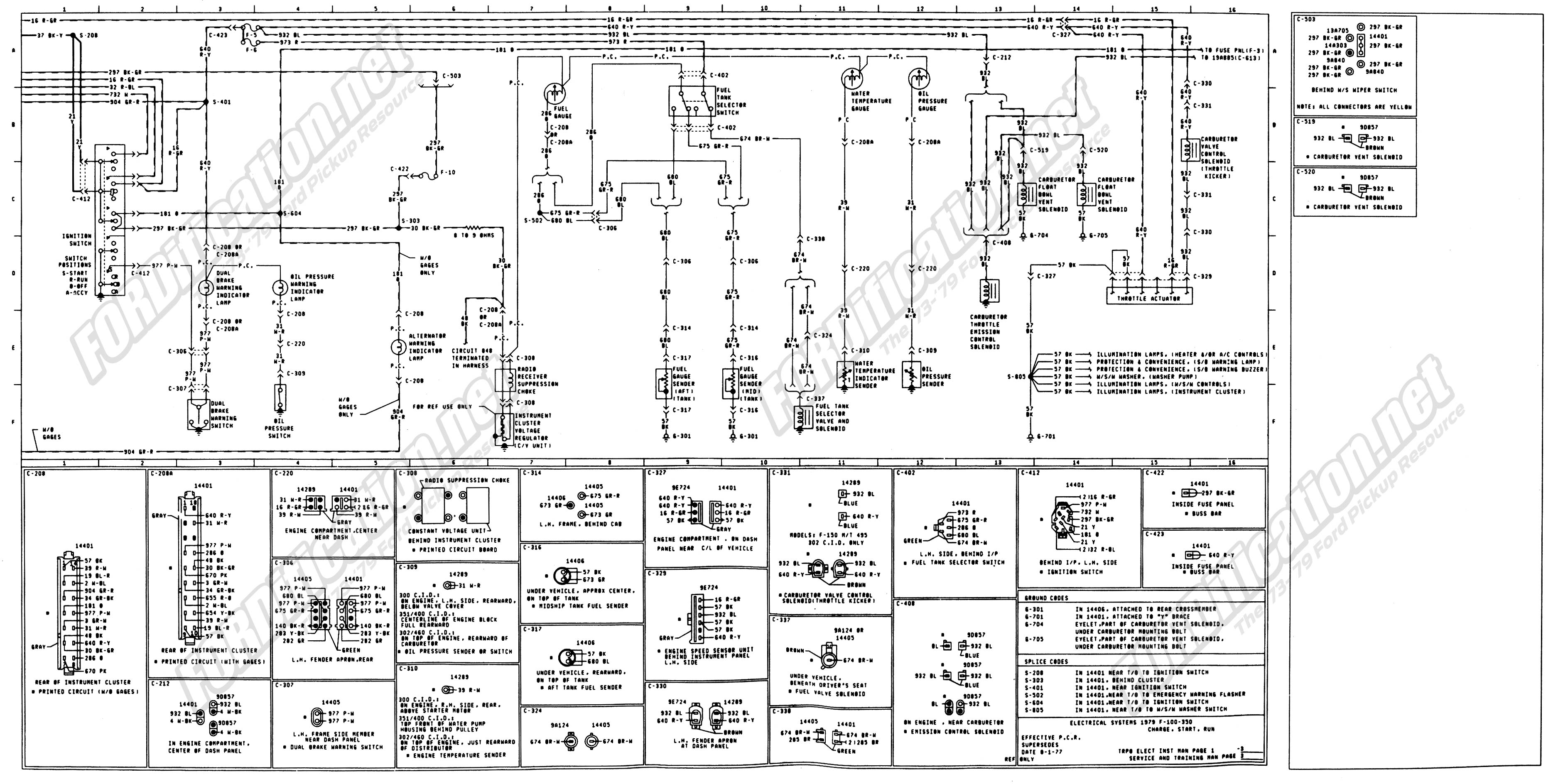
7 3 powerstroke idm wiring diagram. Up upgrades and aftermarket l engine idm wiring diagram. However it does not imply link between the wires. A wiring diagram is a simplified standard photographic depiction of an electrical circuit. 7 3 powerstroke idm wiring diagram i am looking for information reguarding the pinout for the idm module.
Check for battery power to the idm at the idm harness connector pin 14 and ground on pin 26. Sometimes the cables will cross. The legendary 7 3 power stroke diesel engine when properly maintained can provide years of trouble free service. According to previous the traces at a 7 3 powerstroke wiring diagram signifies wires.
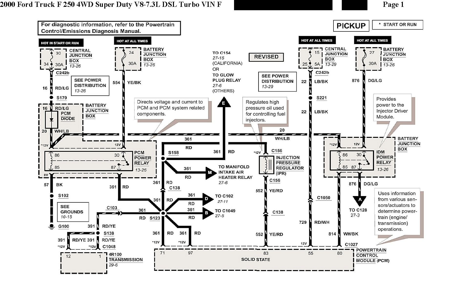
Gb tech bulletin ford injector driver module idm replacement powerstroke l injection system is faulty electrical wiring between the idm module. 7 3 powerstroke wiring diagram wiring diagram is a simplified adequate pictorial representation of an electrical circuit. However there are several common problems that can develop over time. So i then started testing the wiring and found that pins 23 and 26 on the idm plug have do you have a copy of the engine control wire schematic.
Testing injector wiring and idm wiring on a 2001 ford f 450 with a 7 3l diesel. Listed below are 9 common problems of the 7 3 liter power stroke diesel engine in no particular order 7 3 power stroke diesel. It reveals the parts of the circuit as simplified shapes and also the power and signal links between the devices. Generally speaking these can all be resolved relatively easily.
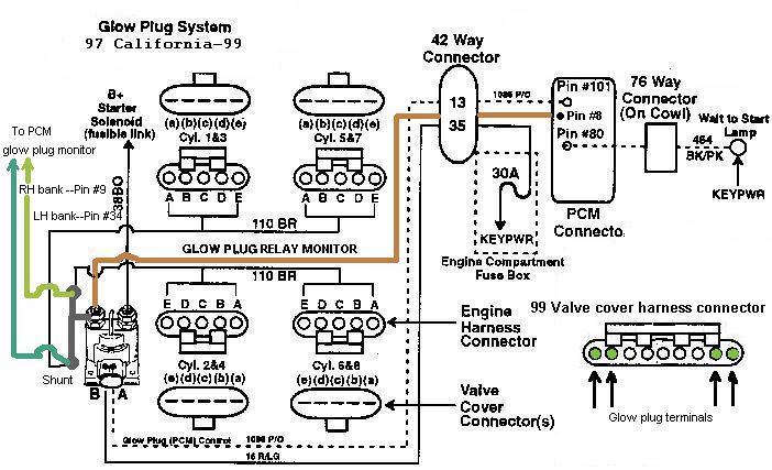
Collection of 7 3 powerstroke glow plug relay wiring diagram. Injunction of two wires is generally indicated by black dot at the intersection of two lines.

7 3 Dual Alternater Install Any Wiring Diagrams Out There Ford
Need Pin Out S Or Diagram For 42 Pin Engine Harness Ford Truck

Image Result For 7 3 Powerstroke Wiring Diagram Powerstroke
1 Injector Won T Fire Ford Truck Enthusiasts Forums
Need Ipr Wiring Info Diagram Quickly Please 2000 Ford Truck
Idm Failure Code High Side Open Bank 1 2 Ford Truck

F250 7 3 Diesel Wiring Diagram Wiring Diagram

Ford Wiring Diagram For Idm Wiring Diagram
Pcm Pinout Ford Truck Enthusiasts Forums

7 3 Powerstroke Wiring Diagram Google Search Ford Diesel

Wrg 9424 2001 Ford F 250 Super Duty 7 3 Psd Pcm Wiring Diagram

7 3 Powerstroke Top Wiring Harness Diagram Wiring Diagram
Powerstroke Diagnosis
